





2026 CNC Machine Center Strategy for Precision Manufacturing
Table of Contents
Introduction
A cnc machine center is no longer simply a machine that follows a program and removes material. In precision manufacturing, it has become the center of a connected production system involving programming, tooling, fixturing, measurement, maintenance, automation, and quality control.
This distinction matters because a machine with impressive specifications can still produce unstable results when the surrounding process is poorly designed. Accuracy depends not only on positioning capability but also on thermal behavior, tool condition, workholding rigidity, program consistency, operator procedures, and inspection feedback.
A practical strategy for 2026 should therefore begin with the production process rather than an isolated machine specification. You need to understand the parts being processed, the tolerances that must be maintained, the expected production mix, the required surface finish, and the level of automation that fits the workflow.
The objective is not to select the most complicated cnc machine center. It is to build a reliable machining system that can repeatedly produce acceptable parts with controlled cycle times, predictable maintenance, and room for future expansion.
What a CNC Machine Center Does
The foundation of a cnc machine center is computer numerical control, which uses programmed instructions to control machine movement and processing operations.
A machining center normally integrates several functions within one controlled platform. Depending on the configuration, it can perform milling, drilling, tapping, boring, slotting, contouring, and other material-removal operations. An automatic tool changer allows different tools to be used during the same machining cycle without repeated manual intervention.
The typical workflow includes:
- Creating or importing a part model.
- Developing the machining process.
- Generating and verifying the CNC program.
- Preparing tools and work offsets.
- Clamping and locating the workpiece.
- Running the machining cycle.
- Inspecting the finished features.
- Adjusting offsets when necessary.
The real advantage is not automation alone. It is the ability to control multiple variables through a repeatable process. When tooling, programs, fixtures, and inspection methods are standardized, the cnc machine center can deliver consistent output across different shifts and production batches.
Building a Precision Strategy Around the Part
A machine strategy should start with the part family. Two components made from the same material may require very different equipment because of differences in geometry, tolerance, wall thickness, feature depth, and clamping accessibility.
Begin by organizing parts according to four factors:
Part Envelope
Identify the maximum length, width, height, and weight of the workpieces. The machine travel should provide enough clearance for fixtures, tools, probing movements, and safe approach paths rather than merely matching the nominal part dimensions.
Feature Complexity
Review the number of machined faces, hole directions, angled surfaces, deep pockets, undercuts, slots, and compound contours. A simple three-axis configuration may be sufficient for flat parts, while additional rotary movement can reduce repositioning for multi-sided components.
Tolerance Sensitivity
Not every dimension requires the same level of control. Separate critical mating features from noncritical surfaces. This helps you assign appropriate tools, inspection frequency, finishing operations, and machine capability.
Production Pattern
A high-volume repeated component creates different priorities from a high-mix workflow. Repeated production emphasizes cycle consistency and automation, while high-mix production requires flexible fixtures, reliable program management, and fast setup procedures.
Choosing the Right Machine Architecture
The structure of a cnc machine center influences accessibility, rigidity, chip removal, setup time, and automation potential. Machine selection should be based on the actual process rather than the assumption that more axes always produce better results.
| Strategic Area | Main Question | Risk When Ignored | Recommended Direction |
|---|---|---|---|
| Axis configuration | How many faces require machining? | Excessive repositioning or unnecessary complexity | Match axis movement to part geometry |
| Spindle system | What materials and tools are used? | Poor cutting stability or inefficient cycles | Balance speed, torque, and tool size |
| Working envelope | What space is needed around the part? | Fixture interference and restricted tool access | Include clamping and clearance requirements |
| Tool capacity | How many tools are needed per process? | Frequent manual tool changes | Plan capacity around complete job families |
| Workholding | How will the part be located repeatedly? | Setup variation and dimensional inconsistency | Standardize locating and clamping points |
| Measurement | How will offsets and dimensions be verified? | Delayed detection of process drift | Integrate probing and inspection routines |
| Automation | Is the process stable enough to automate? | Automated repetition of unstable results | Stabilize the process before expansion |
| Data management | How are programs and revisions controlled? | Wrong program or outdated parameters | Use controlled naming and revision procedures |
A vertical cnc machine center provides straightforward access and is suitable for many general milling, drilling, and tapping operations. A horizontal configuration can support multi-face processing and effective chip evacuation in suitable applications. Additional rotary axes allow angled or multi-sided features to be completed with fewer manual setups.
For long or complex profiles, a 4-axis CNC aluminum profile machining center can support machining from multiple orientations while reducing repeated repositioning. The suitability of this configuration still depends on profile length, feature direction, clamping method, spindle access, and required cycle time.
Managing Accuracy as a Complete Process
Machine positioning accuracy is only one part of finished-component accuracy. A reliable precision strategy treats accuracy as a chain. The result can be affected by the machine structure, spindle condition, toolholder interface, cutter geometry, fixture rigidity, material variation, temperature, probing method, and inspection procedure.
A small amount of variation at several stages can combine into a significant dimensional error. For this reason, production teams should not respond to every deviation by changing a program offset. First determine where the variation originates.
A useful troubleshooting sequence is:
- Confirm that the inspection method is repeatable.
- Check whether the workpiece is located correctly.
- Inspect clamping force and fixture contact surfaces.
- Verify tool length, diameter, wear, and runout.
- Review spindle warm-up and temperature conditions.
- Confirm work offsets and program revisions.
- Check machine geometry if the deviation remains.
This sequence prevents unnecessary corrections. Changing an offset to compensate for a loose fixture, damaged tool, or inconsistent measurement may temporarily move one dimension into tolerance while creating new errors elsewhere.
Matching the Spindle to the Machining Task
Spindle selection should reflect the relationship between material, cutter diameter, cutting depth, feed rate, and surface requirements.
High spindle speed can be beneficial for smaller tools, detailed contours, and materials that support higher cutting speeds. Higher torque at lower rotational speeds may be more important for large tools, deeper cuts, or demanding material-removal operations.
The correct strategy is not to maximize a single specification. It is to define the operating range used by your actual parts.
Consider:
- The most frequently used tool diameters.
- The required cutting speed for the material.
- Roughing and finishing requirements.
- Toolholder type and rigidity.
- Expected spindle operating duration.
- Heat generation during long cycles.
- Surface finish expectations.
- Required acceleration and deceleration.
A spindle that performs well only at the upper end of its speed range may not support heavy cutting efficiently. Conversely, a torque-focused configuration may not be ideal for small tools and fine surface work. The intended process window should guide the decision.
Improving Tooling and Workholding Stability
Tooling and workholding often determine whether the theoretical capability of a cnc machine center can be achieved in daily production.
Tool overhang should be kept as short as the geometry allows. Excessive extension increases deflection and vibration, particularly during side milling or deep-pocket operations. Toolholders and collets should be inspected and cleaned because contamination or wear at the interface can affect runout.
Workholding should locate the component from stable reference surfaces. Clamping force must be sufficient to resist cutting loads without deforming thin sections or delicate profiles. For repeated parts, fixture design should make incorrect loading difficult.
A strong setup standard records:
- Fixture identification.
- Locating surfaces.
- Clamping sequence.
- Recommended clamping pressure.
- Work offset location.
- Tool list and tool life limits.
- Inspection points.
- First-piece approval requirements.
This information reduces dependence on individual memory. It also shortens troubleshooting because the expected setup condition is clearly defined.
Reducing Setup Time Without Sacrificing Control
Reducing setup time does not mean removing verification steps. It means preparing the process so those steps can be completed quickly and consistently.
Offline preparation is one of the most effective approaches. Tools can be assembled and measured before the current job is finished. Programs, drawings, fixtures, inspection instructions, and material can also be prepared in advance.
Standardized work offsets and fixture references help new jobs enter production with fewer manual adjustments. Modular fixtures can support multiple part families when they preserve reliable locating principles.
Digital program control is equally important. Every file should have a clear name, revision status, release date, and part reference. Uncontrolled copies stored on separate devices create a risk that an outdated program will return to production.
Setup reduction should focus on eliminating uncertainty, not simply increasing speed. A ten-minute setup with unclear offsets and unverified tools is less efficient than a controlled fifteen-minute setup that produces an acceptable first part.
Integrating Measurement Into the Machining Cycle
Measurement should not be treated only as a final inspection activity. It can also be used to establish work offsets, verify raw material position, detect tool damage, and monitor process drift.
A workpiece probe can help confirm that the component is correctly loaded before cutting begins. A tool measurement system can detect an unexpected change in tool length or diameter. In-process checks can identify movement before a full batch is affected.
However, measurement automation must be designed carefully. Probe routines need defined acceptance limits, clean measurement surfaces, and a response plan when a result falls outside the expected range.
The strategy should answer three questions:
- What is being measured?
- What decision is made from the result?
- What happens when the result is unacceptable?
Collecting measurements without a defined response adds data but not control. Effective measurement closes the loop between machining, inspection, adjustment, and process improvement.
Using Automation at the Right Stage
Automation can extend machine utilization, reduce repetitive handling, and improve workflow consistency. It may include automatic tool changing, probing, barcode program loading, pallet handling, robotic loading, part identification, or production monitoring.
The process must be stable before unattended operation is expanded. Automation does not correct a weak fixture, uncertain tool life, poor chip control, or unreliable program. It repeats the existing process more consistently, including its weaknesses.
Before increasing automation, confirm that:
- Parts can be loaded in a repeatable orientation.
- Fixtures can tolerate extended production.
- Tool life is predictable.
- Chips are removed reliably.
- Coolant reaches critical cutting zones.
- Programs have been verified.
- Measurement routines can detect abnormal conditions.
- The system has a defined recovery procedure.
A gradual approach is usually more reliable. Begin with program control, probing, tool measurement, and setup standardization. Then add handling automation after the machining process has demonstrated consistent performance.
Creating a Preventive Maintenance System
Precision declines gradually when contamination, lubrication problems, worn interfaces, or thermal behavior are ignored. Preventive maintenance should therefore be connected to machining quality rather than treated only as an equipment service task.
Daily checks can cover lubrication levels, coolant condition, air supply, chip accumulation, toolholder cleanliness, and visible leaks. Scheduled checks may include spindle condition, axis backlash, alignment, tool-change performance, fixture wear, and safety systems.
Maintenance records should capture more than completion dates. They should also document repeated alarms, dimensional trends, unusual sounds, vibration, tool-life changes, and production interruptions.
This information helps distinguish isolated events from developing problems. For example, repeated tool breakage may initially appear to be a tooling issue but could indicate spindle runout, fixture movement, incorrect parameters, or poor chip evacuation.
Maintenance becomes more valuable when it is connected to quality and production data. The purpose is not merely to keep the cnc machine center running. It is to keep the process capable.
Developing a 2026 Implementation Roadmap
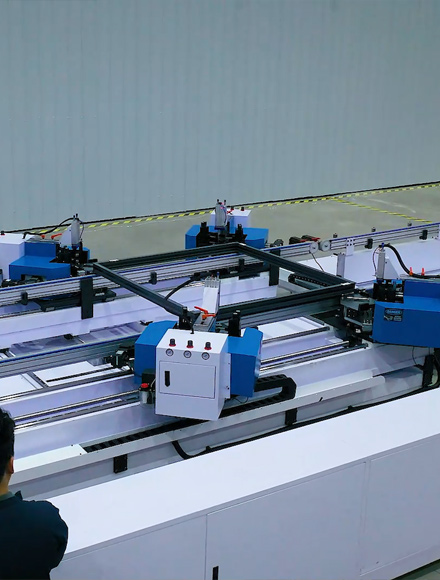
A practical cnc machine center strategy can be implemented in stages.
Stage One: Define the Production Requirement
Document part families, materials, tolerances, feature complexity, batch patterns, surface requirements, and expected working hours. Separate essential requirements from optional capabilities.
Stage Two: Map the Complete Process
Review programming, tooling, workholding, loading, machining, inspection, maintenance, and data handling. Identify where variation or delay currently enters the workflow.
Stage Three: Validate the Configuration
Use representative parts to evaluate machine travel, axis access, spindle performance, tool capacity, fixture clearance, chip control, and measurement requirements. Do not rely on one simple demonstration part.
Stage Four: Standardize the Workflow
Create setup sheets, tool lists, fixture instructions, inspection plans, maintenance schedules, and program revision rules. Train operators around the standardized process.
Stage Five: Measure Real Performance
Track first-part approval, setup duration, cycle stability, tool life, unplanned stops, rework causes, and dimensional trends. These indicators reveal whether the strategy is improving production rather than merely adding technology.
Stage Six: Expand Carefully
After the process is stable, evaluate additional automation, monitoring, pallet handling, or connected production systems. Expansion should solve a verified production constraint.
For applications requiring assessment of travel, spindle configuration, axis movement, tooling, and workflow integration, a structured machine configuration consultation can help align the equipment with the actual processing task.
Conclusion
A successful 2026 cnc machine center strategy should connect equipment capability with process discipline. Accuracy, productivity, and reliability are created by the interaction of the machine, spindle, tooling, fixtures, programs, measurement systems, maintenance procedures, and trained personnel.
The strongest strategy begins with the workpiece. Define the geometry, tolerances, material, production pattern, and inspection requirements before selecting axis count or automation features. Then build a controlled workflow around the machine.
When each stage is standardized and measured, the cnc machine center becomes more than a production asset. It becomes a repeatable manufacturing platform capable of supporting precision, flexibility, and long-term process improvement.
FAQ
What is a cnc machine center?
A cnc machine center is a computer-controlled machine tool that can perform operations such as milling, drilling, tapping, boring, and contouring. It usually combines programmable axis movement with automatic tool changing to process several features in one controlled setup.
How is a cnc machine center different from a CNC milling machine?
A basic CNC milling machine may focus mainly on programmed cutting movement. A cnc machine center generally adds functions such as automatic tool changing, enclosed processing, tool management, probing options, and greater support for completing multiple operations in one setup.
How many axes should a cnc machine center have?
The correct axis count depends on part geometry. Three axes may be sufficient for straightforward surfaces and holes. A fourth or fifth axis can reduce repositioning when parts contain angled features, multiple machined faces, or complex contours requiring better tool access.
What affects the accuracy of a cnc machine center?
Finished-part accuracy is influenced by machine geometry, thermal conditions, spindle condition, tool runout, cutter wear, fixture rigidity, clamping force, program settings, material behavior, and inspection repeatability. These factors should be controlled as one connected process.
How often should a cnc machine center receive maintenance?
Basic inspection should be performed daily, while more detailed maintenance should follow operating hours, machine condition, and the manufacturer’s recommendations. Dimensional trends, alarms, vibration, lubrication, coolant, spindle behavior, and fixture wear should also be recorded.