





Cutter Aluminium Guide: How to Improve Cut Quality and Production Stability
Table of Contents
Introduction
A cutter aluminium machine must do more than separate a profile into two pieces. In precision production, it needs to create consistent lengths, clean edges, controlled angles, and stable results across repeated cycles. These requirements become more demanding when aluminium profiles contain thin walls, hollow chambers, decorative surfaces, or complex cross-sections.
In this article, cutter aluminium refers to equipment used for cutting aluminium bars, extrusions, tubes, frames, panels, and industrial profiles. Depending on the application, the equipment may use a circular saw blade, automated feeding system, CNC positioning unit, angle-control mechanism, or an integrated machining platform.
Many cutting problems are blamed on the blade or machine motor. In practice, cut quality is usually influenced by the entire process, including profile support, clamping pressure, blade condition, feed stability, lubrication, chip evacuation, material temperature, and measurement procedures.
A reliable cutter aluminium strategy therefore begins with the workpiece and production requirement. Once you understand the profile geometry, tolerance, finish expectation, batch pattern, and downstream machining process, you can define a machine configuration that supports stable production instead of relying on specifications alone.
What Does Cutter Aluminium Mean in Industrial Production?
The phrase cutter aluminium can describe several types of equipment, from manually operated saws to automated CNC cutting systems. The correct configuration depends on what material is being processed and what must happen after the cut.
Common workpieces include:
- Aluminium extrusion profiles
- Hollow rectangular or square tubes
- Window and door frame sections
- Structural profiles
- Heat sink profiles
- Decorative trims
- Industrial rails
- Long bars and channels
- Machined frame components
The properties of aluminium make it suitable for many industrial applications, but they also create specific cutting challenges. Aluminium can form long or adhesive chips, mark easily on visible surfaces, and deform when thin sections are clamped too aggressively.
A cutter aluminium machine must therefore balance cutting speed with profile protection. Fast cutting is not valuable when it creates burrs, dimensional variation, damaged surfaces, or frequent stoppages for cleaning.
The most effective systems combine cutting power with controlled material handling. Accurate positioning, rigid support, consistent clamping, suitable tooling, and reliable chip removal are often more important than increasing cutting speed alone.
Start With the Aluminium Profile
Machine selection should begin with the profile rather than the equipment catalogue. Two aluminium components with the same outside dimensions may require different cutting strategies because their internal structures, wall thicknesses, surface treatments, and tolerance requirements are different.
Profile Cross-Section
A solid bar provides continuous material engagement, while a hollow extrusion causes the blade teeth to repeatedly enter and leave the material. Profiles with multiple internal chambers can create vibration and uneven cutting loads.
The machine, blade, and feed strategy should account for:
- Maximum profile width and height
- Minimum and maximum wall thickness
- Number of hollow chambers
- Profile symmetry
- Open or closed cross-sections
- Decorative or coated surfaces
- Areas vulnerable to deformation
Required Cut Length
The positioning system must cover the required material length while maintaining repeatability. Long profiles also require suitable support before and after the cutting zone.
Unsupported material can sag, rotate, or move during cutting. Even when the machine positioning system is accurate, unstable material support can produce inconsistent finished lengths.
Cut Angle
Straight 90-degree cuts are usually less demanding than variable-angle or compound-angle operations. If angled cuts are required, the machine must control both material position and cutting-head orientation.
The angle-setting mechanism should be rigid enough to resist movement during cutting. Small angular deviations can create visible assembly gaps when two profiles are joined.
Match the Machine Type to the Production Task
Not every cutter aluminium system needs the same degree of automation. A machine should match the actual production pattern, part complexity, and handling requirements.
Manual or semi-automatic equipment may be suitable for low-volume work with frequent material changes. Automated feeding and CNC positioning become more valuable when the same lengths are produced repeatedly or when several programmed dimensions are needed within one production run.
Single-Head Cutting Systems
A single-head system cuts one end or one position at a time. It can offer flexibility for varied profile lengths and low-to-medium production volumes.
Its effectiveness depends heavily on positioning accuracy and operator procedures. Standardized stops, digital measurement, and repeatable clamping help reduce variation between parts.
Double-Head Cutting Systems
A double-head system can process both ends of a profile within one controlled setup. This can reduce repeated repositioning and help maintain relationships between overall length and end angles.
The main advantage is not simply speed. By controlling both ends in one setup, the system can reduce accumulated positioning errors and handling variation.
CNC Cutting and Machining Systems
A CNC-controlled system can manage profile positioning, programmed lengths, cutting sequences, angle adjustments, and production records. When cutting is followed by drilling, milling, tapping, or slotting, an integrated 4-axis CNC aluminum profile machining center may reduce transfers between separate machines.
Integration is most valuable when it eliminates repeated alignment and reference-setting. However, a more advanced machine is only beneficial when the workpieces and workflow require those capabilities.
How Blade Selection Affects Cut Quality
The blade is one of the most visible parts of a cutter aluminium process, but blade diameter alone does not determine performance. Tooth geometry, tooth count, kerf width, blade stiffness, material compatibility, and operating condition all affect the result.
A blade with too few active teeth may create rough engagement, vibration, or edge damage. A blade with excessive tooth engagement may generate heat, restrict chip evacuation, and increase cutting resistance.
The correct tooth pattern should allow chips to leave the cutting zone without becoming trapped between the blade and the profile.
Important blade considerations include:
- Profile wall thickness
- Solid or hollow material
- Profile width
- Cutting angle
- Required surface finish
- Cutting speed
- Feed stability
- Machine spindle rigidity
- Blade runout
- Resharpening condition
Blade cleanliness is also important. Aluminium deposits on the cutting edge can change the effective tooth geometry and increase friction. A blade that remains physically intact may still produce poor cuts when its teeth are contaminated, worn, or unevenly sharpened.
Blade inspection should therefore be based on cut performance rather than visual damage alone.
Control Spindle Speed and Feed as One System
Spindle speed and cutting feed should not be adjusted independently. They work together to determine tooth engagement, chip formation, heat generation, vibration, and surface quality.
When feed is too slow, the blade may rub rather than cut efficiently. This can generate heat and encourage material adhesion. When feed is too aggressive, the blade can deflect, the profile may move, and the cut surface can become rough.
A stable cutter aluminium process produces chips that are removed cleanly without excessive noise, vibration, heat, or burr formation.
Operators should observe:
- Chip shape and size
- Blade sound during entry
- Spindle load
- Cut surface pattern
- Burr position
- Profile movement
- Blade temperature
- Cutting-cycle consistency
Changes in these indicators can reveal process drift before dimensional inspection identifies a rejected component.
Feed control should also account for profile geometry. A constant feed rate may not be ideal when the blade moves from thin wall sections into thicker intersections. Controlled feed adjustment can help maintain a more consistent cutting load.
Build Stable Clamping and Material Support
Clamping is one of the most underestimated factors in aluminium cutting. The profile must remain fixed during the cutting cycle, but excessive pressure can deform thin walls or damage visible surfaces.
The most reliable clamping system applies force near stable sections of the profile. Whenever possible, force should be distributed over a suitable contact area instead of being concentrated on a narrow edge.
Soft pads or profile-specific supports can help protect finished surfaces. However, these components must remain clean. Trapped chips can create marks, alter profile position, and reduce clamping consistency.
Material support should control:
- Vertical position
- Side-to-side movement
- Profile rotation
- Sagging
- Exit movement after separation
- Contact with finished surfaces
Long profiles require support on both sides of the cutting zone. The support height should align with the machine reference plane. Even a small height difference can place stress on the profile and influence the final angle.
A stable process should allow the material to be loaded in only one correct orientation. Profile guides, locating blocks, and dedicated fixtures can reduce setup mistakes and improve repeatability across different operators.
Improve Chip Evacuation and Lubrication
Aluminium cutting can generate chips that are lightweight, sharp, and difficult to control. If chips remain near the blade, clamps, measuring stops, or profile supports, they can affect both quality and equipment reliability.
Chip accumulation may cause:
- Surface scratching
- Incorrect positioning
- Clamp interference
- Blade contamination
- Sensor obstruction
- Increased heat
- Inconsistent cutting resistance
- Additional maintenance time
Extraction should capture chips close to the cutting zone. The enclosure and airflow path must guide chips toward the collection system rather than allowing them to spread through the machine.
Lubrication should support cutting without creating excessive residue. Too little lubrication can increase friction and material adhesion. Too much can contaminate finished profiles, attract chips, and make the work area difficult to maintain.
The objective is controlled application. Lubricant should reach the active cutting interface in a consistent amount. Nozzle position, spray pattern, fluid condition, and delivery timing should be included in regular process checks.
Evaluate Accuracy Beyond the Positioning System
A cutter aluminium machine may have a precise positioning system and still produce inconsistent components. Finished-part accuracy is affected by every stage between raw material loading and final measurement.
Key sources of variation include:
| Process Area | Possible Source of Variation | Practical Control Method |
|---|---|---|
| Material positioning | Chips or debris on stops | Clean reference points at defined intervals |
| Profile support | Sagging or uneven roller height | Align supports with the machine reference plane |
| Clamping | Profile movement or deformation | Standardize force and clamp location |
| Blade condition | Wear, contamination, or runout | Inspect cut surface and blade performance |
| Feed motion | Unstable entry into the material | Control acceleration and feed rate |
| Angle setting | Mechanical movement or incorrect reference | Verify using a calibrated reference part |
| Thermal condition | Profile or machine temperature changes | Stabilize conditions before critical production |
| Measurement | Inconsistent inspection method | Define tools, locations, and operator procedure |
| Program control | Wrong dimension or outdated revision | Use controlled program names and revisions |
When a dimension moves outside tolerance, changing the machine offset should not be the first response. The cause may be a dirty stop, loose profile, damaged blade, inconsistent measurement, or unsupported material.
A structured troubleshooting sequence is more reliable:
- Confirm the measurement method.
- Check the material reference position.
- Inspect supports and clamps.
- Examine blade condition and runout.
- Review the programmed dimension.
- Verify the cutting angle.
- Adjust the offset only after other causes are excluded.
This approach prevents an offset correction from hiding a mechanical or process problem.
Protect Surface Quality and Reduce Burrs
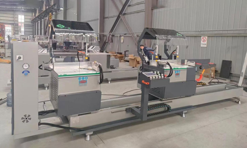
Surface quality is especially important when aluminium profiles remain visible after assembly. Scratches, clamp marks, burrs, and rough cut faces can create additional finishing work or affect the appearance of the final product.
Burr formation is influenced by blade condition, tooth geometry, feed direction, profile support, spindle stability, and material movement.
A burr on one side of the cut may indicate that the blade is exiting an unsupported surface. Burrs distributed across the entire edge may indicate wear, incorrect feed, vibration, or material adhesion.
Surface protection should begin before cutting. Storage racks, transfer rollers, clamps, guides, and collection areas must all be designed to prevent metal-to-metal contact on sensitive surfaces.
Protective film can reduce cosmetic damage, but it should not interfere with clamping or become trapped in the cutting zone. The process should confirm whether the film remains stable under cutting heat and chip movement.
Plan Automation Around a Stable Process
Automation can improve cutter aluminium productivity by controlling material feeding, programmed length changes, cutting sequences, part counting, and unloading. It can also reduce repetitive manual measurements.
However, automation cannot correct unstable clamping, inconsistent material, poor chip control, or unpredictable blade life. It will repeat an unstable process more consistently.
Before introducing higher automation levels, confirm that:
- Material feeds without rotating or jamming.
- Profile variation remains within the support range.
- Clamping does not damage thin walls.
- Blade life is predictable.
- Chips are removed reliably.
- Program revisions are controlled.
- Finished parts can be separated safely.
- Abnormal conditions can be detected.
A gradual implementation often produces better results. Begin with digital length control, recipe storage, automatic clamping, and production counting. More complex loading and unloading systems can be added after the cutting process is proven stable.
Create a Preventive Maintenance Routine
Maintenance should protect cutting accuracy rather than simply prevent machine stoppage. Small changes in blade condition, spindle movement, clamping pressure, support alignment, or sensor cleanliness can gradually reduce process capability.
Daily checks may include:
- Blade condition
- Lubricant supply
- Chip accumulation
- Clamp surfaces
- Safety guards
- Air pressure
- Positioning stops
- Sensor cleanliness
- Unusual sound or vibration
Scheduled inspections can cover spindle runout, blade-flange condition, feeding accuracy, angle-setting mechanisms, support alignment, extraction performance, electrical connections, and moving components.
Maintenance records should include observed changes, not only completed tasks. Repeated burr formation, longer cycle times, rising spindle load, unusual cutting sound, or increased dimensional adjustment can reveal a developing issue.
Connecting maintenance records with quality data creates a more useful system. It helps production teams determine whether a problem is related to tooling, workholding, material, programming, or machine condition.
A Practical Cutter Aluminium Selection Framework
A cutter aluminium configuration should be defined through the complete production requirement.
Begin with these questions:
- What profiles will be processed?
- What are the maximum profile dimensions?
- Are the profiles solid, hollow, or multi-chambered?
- What straight and angled cuts are required?
- What length and angle tolerances must be maintained?
- Are surfaces decorative or protected?
- How often will profile types change?
- What operations occur after cutting?
- Is manual, semi-automatic, or CNC positioning suitable?
- How will chips and finished parts be handled?
A representative production test should include the most difficult profile rather than the easiest sample. The test should evaluate length repeatability, angle stability, edge condition, burr formation, clamping marks, chip evacuation, setup time, and downstream assembly.
For projects requiring evaluation of cutting, drilling, milling, axis control, profile handling, or complete process integration, a structured machine configuration assessment can help connect the equipment specification with the real production task.
Common Cutter Aluminium Problems and Their Causes
Inconsistent Finished Length
Check the material stop, feeding system, clamping sequence, chip contamination, profile movement, and measurement method. Do not assume the positioning system is the only possible cause.
Rough Cut Surface
Inspect blade condition, blade runout, tooth geometry, feed stability, spindle condition, and profile support. A repeating surface pattern can help indicate whether vibration is linked to the blade or workpiece.
Excessive Burrs
Review blade sharpness, exit support, cutting direction, lubrication, feed rate, and material movement. Burr location often provides useful evidence about where instability occurs.
Profile Deformation
Reduce or redistribute clamping pressure. Move the clamp toward a stronger section or use a profile-specific support that prevents the hollow section from collapsing.
Surface Scratches
Inspect rollers, clamps, locating stops, worktables, and collection areas for embedded chips. Cleaning only the cutting zone may not solve damage caused during loading or unloading.
Conclusion
An effective cutter aluminium process depends on more than the blade and motor. Precision cutting is created by the interaction of profile geometry, machine structure, positioning, clamping, support, tooling, lubrication, chip removal, measurement, maintenance, and operator procedures.
The strongest machine strategy begins with the aluminium profile and finished-component requirement. Define the dimensions, wall thickness, cut angles, surface expectations, tolerances, production pattern, and downstream operations before deciding how much automation is required.
Once the process is standardized, cutting performance becomes easier to measure and improve. Stable clamping reduces movement, suitable blade engagement improves edge quality, controlled feeding protects accuracy, and effective chip removal prevents contamination.
A well-planned cutter aluminium system does not simply complete cuts faster. It creates predictable components, supports smoother downstream machining, reduces avoidable rework, and provides a reliable foundation for long-term production.
FAQ
What is a cutter aluminium machine?
A cutter aluminium machine is equipment designed to cut aluminium bars, tubes, extrusions, panels, or industrial profiles. It may use manual positioning, automatic feeding, CNC length control, angle adjustment, and programmed cutting cycles, depending on the production requirement.
Which blade is suitable for cutter aluminium applications?
Blade selection depends on profile size, wall thickness, solid or hollow construction, cutting angle, spindle condition, and required edge finish. The correct blade should maintain stable tooth engagement, remove chips efficiently, and limit vibration, heat, burrs, and material adhesion.
Why does a cutter aluminium machine produce burrs?
Burrs may result from a worn or contaminated blade, incorrect feed, insufficient support, profile movement, spindle runout, poor lubrication, or unstable blade exit. Burr location and direction can help identify whether the main cause is tooling, support, or cutting motion.
How can cutter aluminium length accuracy be improved?
Keep reference stops clean, align material supports, standardize clamping, control program revisions, inspect feed-system repeatability, and use a consistent measurement method. Before changing offsets, verify that chips, profile movement, blade condition, or inspection variation are not causing the error.
Can cutter aluminium equipment handle angled profiles?
Yes. Suitable equipment can produce straight, mitered, or programmed angled cuts. Accuracy depends on the rigidity of the angle-setting mechanism, profile support, clamping stability, blade condition, and reference calibration. Representative profile testing is important before production begins.