





What Makes a Chinese CNC Machine Reliable for Aluminium Processing?
Table of Contents
Introduction
The search for a chinese cnc machine often begins with specifications such as axis travel, spindle speed, motor power, positioning accuracy, and tool capacity. These figures are useful, but they do not provide a complete picture of how a machine will perform during real production.
A reliable CNC machine is the result of several connected elements: mechanical structure, motion components, spindle stability, control software, workholding, tooling, process engineering, quality inspection, operator training, and long-term technical support.
This is particularly important in aluminium profile processing. Long extrusions, hollow chambers, thin walls, coated surfaces, and complex cross-sections can expose weaknesses that may not appear when a machine is tested on a simple solid block.
A strong selection strategy should therefore focus on production evidence rather than isolated specifications. The question is not simply whether a chinese cnc machine can move accurately. You need to determine whether it can repeatedly produce your parts, protect sensitive surfaces, manage chips, maintain stable tolerances, and support changes in production over time.
This article presents a practical framework for evaluating CNC equipment for aluminium cutting, drilling, milling, slotting, tapping, and multi-face profile processing.
Why the Term Chinese CNC Machine Covers Many Equipment Types
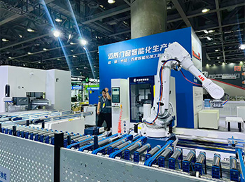
A chinese cnc machine is not one standardized machine category. The phrase may refer to compact drilling equipment, profile machining centers, end milling machines, CNC cutting saws, multi-axis machining systems, or complete automated production lines.
The common foundation is computer numerical control, which uses programmed instructions to control machine movement, spindle operation, tool paths, and supporting functions.
For aluminium profile production, common equipment configurations include:
- CNC drilling and milling machines
- Three-axis machining centers
- Four-axis profile machining centers
- Five-axis end milling machines
- CNC double-head cutting saws
- Sawing and milling workstations
- Automated door and window production lines
- Barcode-controlled machining systems
The correct machine category depends on the workpiece rather than the broad search term. A short profile requiring holes on one face creates a very different production requirement from a long extrusion requiring milling, drilling, slotting, and machining on multiple sides.
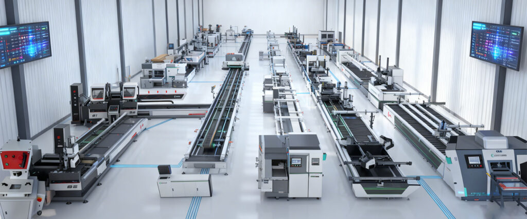
The manufacturer’s current equipment range should also match the required process. A product portfolio covering cutting, drilling, milling, end machining, corner assembly, and intelligent production lines provides more opportunities to integrate related operations into one coordinated workflow.
Start With the Part, Not the Machine Specifications
The most reliable way to evaluate a chinese cnc machine is to begin with representative parts. A specification sheet describes potential machine capability, but the workpiece determines whether that capability is useful.
Start by documenting the following requirements.
Profile Envelope
Record the maximum and minimum profile length, width, height, and weight. Include the space required for fixtures, clamps, tools, probing movements, and loading clearance.
A machine travel value should not be treated as the maximum usable part size. Toolholder dimensions, rotary movement, clamps, and safe approach distances reduce the practical working area.
Cross-Section Structure
Identify whether the profile is solid, hollow, open, closed, symmetrical, or divided into multiple chambers. Thin internal walls can vibrate or deform when machining forces are not controlled.
Complex cross-sections may also require dedicated support blocks to prevent movement during drilling or milling.
Machining Features
List every required operation, including:
- Through holes
- Blind holes
- Slots
- Pockets
- End-face milling
- Drainage channels
- Threaded holes
- Lock and handle openings
- Angled features
- Multi-side machining
This feature map helps determine the required axes, spindle orientation, tool capacity, and number of setups.
Surface Requirements
Anodized, coated, polished, or decorative profiles need careful handling. Clamps, supports, transfer rollers, chips, and unloading systems must not damage visible surfaces.
A technically accurate machine can still create unacceptable parts if material handling is poorly designed.
Match the Axis Configuration to the Process
Additional axes can improve access and reduce repeated setups, but more axes do not automatically create a better production process.
A three-axis machine controls movement along the X, Y, and Z directions. It is often suitable for holes, slots, pockets, and contours that can be reached from one main orientation.
A rotary axis allows the workpiece or machining head to access additional faces. This can reduce manual repositioning and preserve relationships between features on different sides.
A 4-axis CNC aluminum profile machining center can support long-profile machining, complex holes, grooves, and multi-orientation operations using servo-controlled motion, a high-speed spindle, and automatic tool changing. The suitability of this configuration still depends on profile geometry, required access, fixture design, and production volume.
Five-axis equipment may be appropriate when the process requires more flexible tool orientation, complex end-face machining, or compound angles. However, a five-axis system may add unnecessary programming and maintenance complexity when the parts only require straightforward three-face machining.
The best axis configuration is the lowest level of complexity that can complete the required operations reliably with controlled setups.
Evaluate Precision as a Complete Capability Chain
Positioning accuracy is often treated as the main indicator of machine quality. In practice, finished-part accuracy depends on a longer capability chain.
That chain includes:
- Machine-bed rigidity
- Linear guide and screw condition
- Servo response
- Spindle runout
- Toolholder condition
- Tool geometry
- Fixture stability
- Profile consistency
- Thermal behavior
- Program and offset control
- Inspection repeatability
A weakness in any link can affect the final dimension.
For example, a machine may position the spindle accurately while a thin profile moves under cutting pressure. The measured hole position will then be incorrect even though the axis system performed as programmed.
A useful machine assessment should therefore include both geometric tests and representative part tests.
| Evaluation Area | Evidence to Review | Why It Matters |
|---|---|---|
| Axis repeatability | Repeated movement to the same position | Shows motion-system consistency |
| Spindle runout | Measurement at the spindle and tool | Influences hole size and surface finish |
| Test-part dimensions | Results from representative profiles | Demonstrates complete process capability |
| Multi-face alignment | Relationships between features on different sides | Reveals rotary-axis and fixture accuracy |
| Thermal stability | Dimensions measured during extended operation | Shows whether accuracy changes over time |
| Surface finish | Milling patterns and edge condition | Indicates vibration, tooling, and spindle stability |
| Setup repeatability | Results after unloading and reloading | Evaluates fixture and locating consistency |
| Program control | Revision and offset procedures | Prevents avoidable production variation |
A single successful sample is not enough. The machine should repeat the same result across multiple parts, tool changes, setups, and operating periods.
Assess Machine Structure and Motion Components
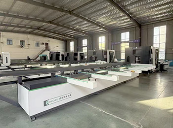
The mechanical structure determines how well a chinese cnc machine resists cutting forces, acceleration, vibration, and long-term wear.
A stable machine bed should provide sufficient rigidity for the intended process. The requirement is different for light drilling, high-speed slotting, deep milling, and heavy end-face machining.
Important structural areas include:
Machine Bed
An integrated or reinforced base can improve stability by reducing deformation between connected components. The bed should support the working length without excessive vibration or misalignment.
Linear Motion System
Guideways, ball screws, gear racks, bearings, and servo systems should work as one coordinated motion platform. Component brand names alone are not enough; installation quality, preload, alignment, lubrication, and protection also matter.
Gantry or Spindle-Carrying Structure
Long-travel profile machines need a structure that maintains alignment throughout the working range. The machine should not perform well only near the center of travel.
Protective Systems
Covers, seals, lubrication, chip guards, and cable management influence long-term reliability. Aluminium chips can enter moving components, sensors, and guide systems when protection is inadequate.
The assessment should consider how the machine performs after months of production, not only how smooth it appears during an initial demonstration.
Match the Spindle and Tooling to Aluminium Machining
Aluminium machining often uses high spindle speeds, sharp cutting tools, and efficient chip removal. However, spindle speed alone does not determine productivity.
The spindle must provide stable rotation throughout the intended operating range. It should also support the required tool diameters, cutting depths, feed rates, and duty cycles.
Evaluate:
- Maximum and continuous spindle speed
- Torque across the usable speed range
- Toolholder interface
- Spindle cooling
- Bearing design
- Runout
- Acceleration time
- Noise and vibration
- Tool-change compatibility
- Maintenance requirements
Tooling should be selected according to the aluminium alloy, profile wall thickness, feature depth, and required finish. Excessive tool overhang can create deflection and chatter, while unsuitable flute geometry can restrict chip evacuation.
Tool capacity should be based on complete part families. A machine may require drills, end mills, slot cutters, tapping tools, chamfering tools, and special profile cutters within one cycle.
An automatic tool changer is valuable when it removes repeated manual intervention. However, its reliability, tool identification, change time, and collision protection should be tested under real production conditions.
Examine Workholding and Profile Support
Workholding is often the difference between theoretical machine accuracy and stable production results.
Aluminium profiles can be difficult to clamp because they may be long, hollow, thin-walled, asymmetrical, or sensitive to surface damage. Too little force allows movement. Too much force can deform the profile.
A suitable clamping system should:
- Locate the profile from consistent reference surfaces
- Apply force near structurally stable areas
- Prevent rotation and lifting
- Avoid damaging coated surfaces
- Accommodate reasonable profile variation
- Provide tool clearance
- Support rapid loading
- Make incorrect orientation difficult
Long profiles also require support beyond the main machining area. Misaligned rollers or support tables can create bending stress, affect feature position, and cause the workpiece to shift when clamps are released.
Profile-specific supports may be needed for hollow or irregular cross-sections. These supports should be easy to clean because trapped chips can change the locating position or scratch the workpiece.
The fixture should be evaluated with the most difficult profile, not only a simple rectangular section.
Review CNC Control, Software, and Data Management
The control system determines how easily operators can create, load, verify, and manage machining programs.
A reliable chinese cnc machine should provide more than axis movement. Its software should support the daily workflow of profile identification, job preparation, tool management, offset control, and program revision.
Useful capabilities may include:
- Graphical programming
- Automatic G-code generation
- CAD or CAM data import
- Barcode scanning
- Recipe storage
- Tool libraries
- Machining simulation
- Collision warnings
- User permission levels
- Production records
- Remote diagnosis
- ERP or MES connectivity
The interface should suit the skill level of the production team. A highly flexible system can become inefficient when every simple part requires specialist programming.
Program management is equally important. Each file should have a controlled name, part reference, revision, release status, and tool list. Old or unverified programs should not remain available without clear identification.
The website’s range of CNC aluminium processing equipment includes profile cutting, drilling, milling, end machining, bending, corner processing, and automated production systems, illustrating how software and process integration can extend beyond one isolated machine.
Use Representative Production Tests
A machine demonstration should reproduce the intended process as closely as possible.
Simple test blocks may show basic axis movement and surface finish, but they do not reveal how the equipment handles long profiles, thin walls, coated surfaces, multiple tools, angled features, or repeated loading.
A representative test should include:
- A real or equivalent profile
- Critical wall thicknesses
- The most difficult feature orientation
- Multiple tool changes
- Required machining depth
- Expected cycle sequence
- Actual clamping method
- Inspection of critical dimensions
- Repeated parts
- Extended machine operation
Record the results rather than relying on visual impressions.
Useful test indicators include first-part accuracy, repeatability, surface finish, burr formation, setup time, cycle consistency, tool-change reliability, spindle load, chip accumulation, and operator intervention.
When several machine configurations are being assessed, use the same profile, program objectives, inspection tools, and acceptance criteria. Otherwise, the comparison will be influenced by different testing conditions.
Verify Manufacturing and Quality-Control Evidence
A reliable manufacturer should be able to explain how the machine is designed, assembled, inspected, tested, and documented.
Useful evidence includes:
- Machine assembly procedures
- Component inspection records
- Axis calibration reports
- Spindle inspection methods
- Electrical testing
- Safety checks
- Test-machining records
- Final inspection documentation
- Software revision control
- Traceable machine identification
The strongest evidence is specific to the actual machine configuration rather than a general company presentation.
It is also useful to understand which parts are designed and produced internally, which components are sourced, and how incoming components are inspected.
A manufacturer that can clearly explain failure modes and corrective procedures often provides more confidence than one that only describes machine advantages.
Ask how the team responds when positioning accuracy changes, a spindle alarm appears, a tool changer loses position, or software data becomes inconsistent. The quality of these answers reveals practical engineering experience.
Plan Installation, Training, and Long-Term Support
Machine reliability depends partly on what happens after delivery.
Installation should confirm machine leveling, electrical conditions, compressed-air quality, lubrication, safety systems, axis movement, spindle operation, program transfer, and machining accuracy.
Training should cover more than basic start and stop functions. Operators and maintenance personnel may need instruction in:
- Program loading
- Work-offset setting
- Tool measurement
- Fixture setup
- Alarm interpretation
- Daily inspection
- Lubrication checks
- Chip management
- Backup procedures
- Preventive maintenance
- Basic troubleshooting
Technical documentation should be understandable and match the delivered machine. Electrical diagrams, pneumatic diagrams, component lists, maintenance schedules, software instructions, and spare-part references should use consistent machine identification.
Remote diagnosis can shorten response time, but it should not replace clear documentation and local troubleshooting capability. The production team should be able to resolve routine issues without depending on external support for every interruption.
Spare-part planning should focus on operational risk. Sensors, switches, seals, lubrication components, pneumatic parts, and frequently used tooling interfaces may deserve more attention than rarely failing structural components.
Common Errors When Evaluating a Chinese CNC Machine
Comparing Only Headline Specifications
Two machines with similar travel and spindle speed may differ significantly in rigidity, assembly quality, software, fixture design, and process stability.
Selecting More Axes Than the Process Requires
Unnecessary complexity can increase programming effort, maintenance needs, and collision risk without improving the finished part.
Ignoring Profile Support
A long profile can sag or rotate outside the machining area, causing errors that are incorrectly blamed on the control system.
Testing Only One Part
One successful component does not prove repeatability. Test multiple parts, setups, tools, and operating periods.
Treating Automation as a Solution to Process Instability
Automation repeats the existing process. It cannot correct weak clamping, unpredictable tool life, poor chip evacuation, or uncontrolled programs.
Overlooking Software Workflow
A mechanically capable machine may still create delays when program preparation, barcode loading, tool management, or revision control is difficult.
Leaving Service Planning Until the End
Installation, documentation, training, diagnostics, and spare parts should be evaluated at the same time as the machine configuration.
A Practical Qualification Framework
A chinese cnc machine can be evaluated through three connected layers.
Layer One: Process Fit
Confirm that the machine can accommodate the profile dimensions, feature directions, tolerances, materials, surface requirements, and production pattern.
Layer Two: Technical Evidence
Review machine structure, axis motion, spindle behavior, tooling, fixtures, software, safety systems, quality records, and representative test results.
Layer Three: Lifecycle Support
Assess installation planning, operator training, documentation, maintenance procedures, remote diagnosis, spare parts, and future process expansion.
A machine should progress through all three layers before final approval. Strong performance in one area does not compensate for major weaknesses in another.
The result should be a documented qualification record containing the required process, selected configuration, test conditions, measured results, unresolved risks, training scope, and acceptance criteria.
Conclusion
A reliable chinese cnc machine should be evaluated as a complete production system rather than a collection of attractive specifications.
The process starts with the workpiece. Profile dimensions, cross-section structure, machining features, tolerances, surface requirements, and production patterns determine the appropriate machine architecture.
The next step is technical verification. Machine rigidity, motion components, spindle stability, tooling, workholding, software, chip control, and inspection methods must work together to produce repeatable parts.
Finally, long-term performance depends on installation, training, documentation, preventive maintenance, diagnostics, and technical support.
The strongest decision is supported by representative test parts and measurable evidence. When the machine is matched carefully to the process, it can provide stable aluminium machining, controlled production, flexible program management, and a foundation for future automation.
FAQ
What is a chinese cnc machine?
A chinese cnc machine is CNC-controlled manufacturing equipment produced by a Chinese manufacturer. The term can describe cutting saws, drilling and milling machines, profile machining centers, end milling systems, multi-axis equipment, or complete automated production lines.
Is a chinese cnc machine suitable for aluminium profiles?
Yes, when the machine structure, spindle, tooling, clamping, software, and working range are designed for aluminium profiles. Representative machining tests should confirm dimensional repeatability, multi-face alignment, surface finish, chip evacuation, and profile protection.
How can CNC machine accuracy be verified?
Review calibration records and machine repeatability, then machine several representative profiles. Measure critical dimensions, hole positions, relationships between faces, surface finish, and setup repeatability. Testing should include tool changes and extended operation.
Which axis configuration is suitable for aluminium machining?
Three axes may be sufficient for features reached from one direction. A rotary fourth axis can reduce manual repositioning for multi-face profiles. Five-axis equipment may suit complex angles and end machining. The configuration should follow part geometry.
What support should be confirmed before machine installation?
Confirm site requirements, installation procedures, operator training, maintenance documentation, software backup, remote diagnosis, spare-part identification, and acceptance testing. Responsibilities and response procedures should be recorded before production begins.