





CNC Machining Center vs CNC Milling Machine: A Practical Comparison
Table of Contents
Introduction
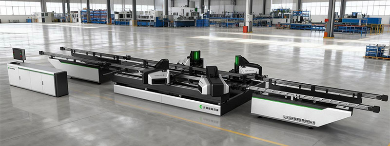
A cnc machining center and a CNC milling machine may appear similar because both use programmed axis movements and rotating cutting tools to remove material. However, their production capabilities, automation levels, tooling systems, setup requirements, and suitable applications can be significantly different.
The distinction is important when you need to process aluminium profiles, structural sections, frame components, plates, or precision parts. Selecting equipment based only on spindle speed or axis travel may result in unnecessary complexity, limited production flexibility, or repeated manual operations.
A conventional CNC milling machine may be suitable for straightforward milling, drilling, and slotting tasks. A cnc machining center usually integrates automatic tool changing, enclosed machining, advanced control functions, workpiece measurement, tool management, and multi-operation processing within one coordinated system.
This does not mean that every machining center is automatically better than every milling machine. The most effective configuration depends on part geometry, production volume, tolerance requirements, tool variety, setup frequency, material handling, and future automation plans.
The practical question is not which machine has the longest specification list. It is which system can complete your real parts with stable quality, controlled setup time, predictable maintenance, and minimal unnecessary handling.
What Is a CNC Machining Center?
A cnc machining center is a computer-controlled machine tool designed to complete several machining operations within one setup. It may perform milling, drilling, boring, tapping, pocketing, contouring, slotting, and chamfering by automatically selecting different tools from a tool magazine.
Its foundation is computer numerical control, which uses programmed instructions to manage machine movement, spindle functions, feed rates, tool changes, and supporting operations.
A typical machining cycle may include:
- Locating and clamping the workpiece.
- Loading the correct machining program.
- Establishing workpiece and tool offsets.
- Selecting the first cutting tool.
- Completing roughing and finishing operations.
- Changing tools automatically.
- Measuring selected features when probing is available.
- Returning the machine to a safe unloading position.
The main advantage is process integration. Multiple features can be completed without repeatedly moving the workpiece between separate machines.
Reducing workpiece transfers can protect the relationship between holes, surfaces, slots, and reference edges. It can also reduce the risk of loading mistakes, accumulated positioning errors, and waiting time between operations.
What Is a CNC Milling Machine?
A CNC milling machine also uses programmed movement to control a rotating cutting tool. Depending on its design, it may process flat surfaces, holes, grooves, pockets, contours, and simple three-dimensional forms.
The term can describe a wide range of machines. Some are compact systems intended for lighter work, while others provide rigid structures, advanced controllers, and multiple axes.
This is where terminology becomes less clear. A sophisticated CNC milling machine with an automatic tool changer and enclosed working area may also be described as a machining center. Manufacturers and industries do not always use the two terms in exactly the same way.
For a practical comparison, the important issue is not the label printed on the machine. You should examine whether the equipment includes the production functions your process requires.
These functions may include:
- Automatic tool changing
- Multiple tool storage
- Workpiece probing
- Tool measurement
- Rotary-axis control
- Chip evacuation
- Coolant management
- Program storage
- Production monitoring
- Automated loading support
A machine should be evaluated by its complete configuration and demonstrated process capability rather than its category name alone.
CNC Machining Center and CNC Milling Machine Compared
The following table summarizes the differences that usually have the greatest effect on production.
| Evaluation Area | CNC Machining Center | CNC Milling Machine | Production Impact |
|---|---|---|---|
| Tool changes | Usually automatic | May be manual or automatic | Affects unattended cycle time |
| Tool capacity | Multiple tools in a magazine | Often fewer tools | Determines operation flexibility |
| Process integration | Designed for several operations | May focus on simpler milling tasks | Influences workpiece transfers |
| Axis options | Commonly supports additional rotary axes | Often based on three linear axes | Affects multi-face access |
| Work enclosure | Usually fully enclosed | Depends on machine design | Controls chips and coolant |
| Measurement | Probing options are common | May require manual inspection | Affects offset control |
| Automation | Easier to connect with handling systems | May require additional integration | Influences future expansion |
| Programming | Supports complex multi-tool cycles | Can be simpler for basic work | Affects training requirements |
| Setup | More planning but fewer transfers | Simpler for individual operations | Changes total production time |
| Suitable workflow | Repeated multi-operation production | Basic or flexible milling work | Should match the actual part family |
The table should be treated as a general framework rather than a fixed rule. Individual machine configurations can overlap.
For example, a basic machining center may be less suitable for a long aluminium extrusion than a dedicated profile milling machine. Similarly, a well-designed CNC milling system may outperform a general machining center when it is optimized for one specific operation.
Compare the Complete Production Cycle
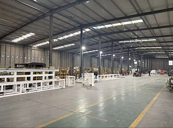
Machine cycle time is only one part of production efficiency. A shorter cutting cycle does not necessarily create a shorter total process.
The complete production cycle may include material preparation, loading, alignment, clamping, program selection, machining, tool changes, measurement, unloading, cleaning, and transfer to the next workstation.
Suppose a component requires drilling, slotting, end milling, and tapping. A basic CNC milling machine may complete each operation accurately, but several tools could require manual replacement. The profile may also need to be removed and repositioned to reach another face.
A cnc machining center may complete the same features using stored tools and controlled axis movement. Its individual machining operations may not always be faster, but the reduction in manual intervention and repeated setup can improve total throughput.
The correct comparison should therefore measure:
- Time required to prepare the job
- First-part approval time
- Number of manual tool changes
- Number of workpiece repositioning steps
- Inspection frequency
- Operator intervention
- Waiting time between operations
- Rework caused by setup variation
This process-level view is more useful than comparing rapid-traverse speed or spindle power in isolation.
Match the Axis Configuration to Part Geometry
Axis count determines how the tool and workpiece can move relative to each other.
A three-axis system moves along the X, Y, and Z directions. It can process many holes, slots, pockets, and contours when the features are accessible from one main orientation.
A fourth axis adds rotary movement. This can allow several sides of a profile to be machined without removing and manually repositioning it.
For long profiles requiring holes, grooves, slots, and multi-side operations, a 4-axis CNC aluminum profile machining center can reduce repeated clamping and improve relationships between features on different faces.
A five-axis configuration provides additional tool orientation or workpiece rotation. It is useful for compound angles, complex end features, difficult tool access, and parts that would otherwise require several fixtures.
More axes also create additional considerations:
- More complex programming
- Greater collision risk
- Additional calibration procedures
- More demanding operator training
- Increased fixture planning
- More detailed maintenance
The appropriate axis count is the simplest configuration capable of completing the required geometry with controlled setups.
Understand the Role of the Automatic Tool Changer
The automatic tool changer is one of the main features separating a cnc machining center from a basic milling setup.
A single component may require several tools, including drills, end mills, slot cutters, tapping tools, chamfering cutters, and finishing tools. Manually replacing each tool adds time and introduces opportunities for incorrect tool installation or offset entry.
An automatic tool changer allows the machining program to select tools in a planned sequence.
Its value depends on more than change speed. You should evaluate:
- Tool-magazine capacity
- Maximum tool diameter and length
- Toolholder compatibility
- Tool identification
- Change-position repeatability
- Tool interference
- Tool-life management
- Recovery after an interrupted change
Tool capacity should be planned around complete part families rather than one demonstration component. A magazine that holds enough tools for one simple part may require frequent manual intervention when production changes to a more complex job.
Reliable tool management also requires controlled offset records. The machine must know the actual length and diameter of each installed tool. Incorrect offset data can cause dimensional errors or collisions even when the mechanical tool change is completed correctly.
Evaluate Accuracy as a Process Chain
The positioning accuracy shown on a machine specification does not directly guarantee finished-part accuracy.
Machining results are influenced by a complete process chain that includes:
- Machine-bed rigidity
- Guideway and drive condition
- Spindle runout
- Toolholder quality
- Cutter wear
- Tool overhang
- Fixture rigidity
- Clamping force
- Workpiece deformation
- Thermal variation
- Program accuracy
- Measurement repeatability
A machine axis may reach the programmed position while the workpiece moves under cutting pressure. The final feature will then be incorrect even though the servo system followed the program accurately.
Thin-walled aluminium profiles require particular attention. Excessive clamping pressure can deform the section, while insufficient force may allow vibration or movement. When the clamp is released, the profile may return toward its original shape and change the measured dimension.
A useful accuracy test should include repeated components, multiple tool changes, reloading, extended machine operation, and measurement of features on different faces.
One accurate sample demonstrates possibility. Repeated results demonstrate process capability.
Compare Spindle Performance Within the Real Cutting Range
Spindle speed is often treated as the primary indicator of machining performance. In reality, the spindle must be matched to the tool diameter, material, cutting depth, feed rate, and required finish.
Aluminium machining frequently benefits from higher spindle speeds and efficient chip evacuation. However, stability remains more important than the maximum speed shown on a data sheet.
Spindle evaluation should consider:
- Continuous operating speed
- Torque throughout the usable range
- Acceleration and deceleration
- Cooling method
- Bearing stability
- Toolholder interface
- Runout
- Noise
- Vibration
- Duty cycle
A spindle that performs well only at its maximum speed may not support larger cutters or heavier operations effectively. A torque-focused spindle may be suitable for deeper cuts but less efficient for small tools and detailed high-speed work.
The correct approach is to identify the tools most frequently used in actual production. The machine should perform reliably across that operating range rather than being optimized around one impressive value.
Examine Workholding and Material Support
A machining center can only maintain accuracy when the workpiece remains stable.
Short solid parts may be relatively easy to clamp. Long aluminium profiles, hollow extrusions, and irregular frame sections require more careful workholding.
The fixture must control:
- Vertical position
- Lateral movement
- Rotation
- Lifting
- Longitudinal movement
- Deformation
- Surface protection
Clamps should apply force near structurally stable areas. Profile-specific support blocks may be required for hollow sections or complex cross-sections.
Long components also need correctly aligned support beyond the machining area. A profile that sags under its own weight can shift when it is clamped, machined, or released.
Cleanliness is part of fixture accuracy. Chips trapped beneath a locating surface can change the workpiece position. Chips embedded in clamp pads or support rollers can also damage decorative surfaces.
A repeatable fixture should make incorrect loading difficult. Clear reference points, loading orientation, clamp sequence, and support positions should be documented in the setup instructions.
Control Chips, Coolant, and Heat
Effective chip management protects both machining quality and equipment reliability.
Aluminium chips can accumulate around tools, clamps, guide systems, sensors, and locating surfaces. Recirculated chips may scratch finished profiles or be pulled back into the cutting zone.
Poor chip evacuation can cause:
- Tool recutting
- Increased heat
- Surface marks
- Unstable cutting loads
- Sensor contamination
- Incorrect workpiece positioning
- Additional cleaning time
Coolant or controlled lubrication can reduce friction and support chip removal. The application method should match the cutter, operation, and workpiece.
Excessive fluid may create residue and attract chips, while insufficient lubrication may increase material adhesion to the tool.
Thermal stability should also be considered. Spindle temperature, ambient conditions, long machining cycles, and repeated cutting can affect dimensions. Critical production should begin after a consistent warm-up routine rather than immediately after the machine has been inactive.
Plan Automation After Stabilizing the Process
A cnc machining center can support automated tool changes, barcode loading, program selection, probing, material handling, part identification, and production monitoring.
Automation should be introduced after the machining process is stable.
It cannot correct:
- Weak workholding
- Incorrect programs
- Unpredictable tool life
- Poor chip evacuation
- Inconsistent raw material
- Uncontrolled offsets
- Inadequate maintenance
Automating an unstable process simply allows the same problems to occur with less supervision.
A gradual implementation is often more reliable. Program revision control, digital tool management, probing, and standardized fixtures can be established first. Material loading, unloading, and extended unattended operation can follow after repeatability has been demonstrated.
The broader range of CNC aluminium processing equipment shows how cutting, drilling, milling, end machining, and related processes can be organized around different levels of production integration.
Use Representative Parts for Machine Validation
A machine demonstration should use a part that represents the most demanding production conditions.
Testing only a simple block may confirm basic machine movement, but it does not reveal how the system handles long profiles, thin walls, multiple sides, coated surfaces, frequent tool changes, or complex clamping.
A useful validation test should include:
- The actual or equivalent production material.
- Critical feature dimensions.
- The required surface finish.
- Multiple tools.
- A realistic fixture.
- The expected machining sequence.
- Repeated loading.
- Several finished components.
- Extended machine operation.
- Documented inspection results.
The test should measure setup time, first-part accuracy, cycle consistency, multi-face alignment, tool-change reliability, burr formation, surface condition, and operator intervention.
When comparing different configurations, use the same part, measurement method, acceptance criteria, and production sequence. Otherwise, the results may reflect different test conditions rather than real machine capability.
Build a Preventive Maintenance Routine
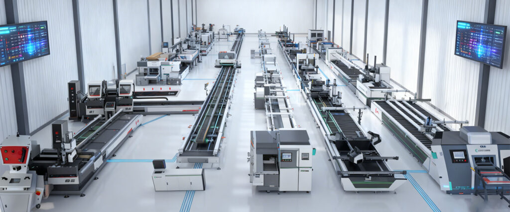
A cnc machining center requires structured maintenance to preserve accuracy and availability.
Daily checks can include:
- Lubrication supply
- Coolant or lubrication condition
- Chip accumulation
- Toolholder cleanliness
- Clamp condition
- Air pressure
- Sensor cleanliness
- Unusual sound
- Visible leaks
- Safety functions
Scheduled inspection should cover spindle runout, axis backlash, tool-change operation, fixture wear, support alignment, electrical connections, protective covers, and calibration status.
Maintenance records should document observations rather than only confirming that a task was completed. Increasing spindle load, changing surface patterns, repeated alarms, shorter tool life, or frequent offset corrections may reveal a developing problem.
Connecting maintenance records with inspection and production data helps determine whether variation originates from the tool, fixture, machine, program, material, or measurement process.
Conclusion
The difference between a cnc machining center and a CNC milling machine is not defined by one feature. It is determined by the complete combination of tooling, axis movement, automation, measurement, workholding, software, chip control, and process integration.
A CNC milling machine may be the right solution for straightforward operations, frequent job changes, or processes that do not require many tools. A cnc machining center becomes more valuable when several operations must be completed in one setup, tool changes need to be automated, or feature relationships must be maintained across multiple faces.
The decision should begin with the workpiece. Define its size, geometry, material, tolerance, surface condition, feature directions, and production pattern. Then evaluate the complete cycle rather than focusing only on cutting speed.
When the machine architecture matches the part and the surrounding process is standardized, a cnc machining center can reduce repeated handling, improve consistency, support automation, and provide a stable platform for precision manufacturing.
FAQ
What is a cnc machining center?
A cnc machining center is a computer-controlled machine tool that performs milling, drilling, tapping, boring, and related operations. It usually includes automatic tool changing, multiple-axis movement, program storage, and an enclosed machining area.
Is a CNC machining center the same as a CNC mill?
The terms sometimes overlap, but a machining center normally provides greater process integration. It commonly includes a tool magazine, automatic tool changer, enclosure, chip management, measurement options, and support for multi-operation production.
How many axes does a cnc machining center need?
Three axes are suitable for many single-orientation features. A fourth axis can reduce manual repositioning for multi-face parts. Five-axis equipment supports complex angles and tool access. The required configuration depends on part geometry.
What affects CNC machining center accuracy?
Accuracy depends on machine geometry, spindle runout, tool condition, fixture rigidity, clamping pressure, thermal behavior, program offsets, workpiece stability, and inspection repeatability. These factors should be managed as one process.
Can a cnc machining center process aluminium profiles?
Yes. The machine must provide suitable travel, spindle performance, tooling, workholding, profile support, lubrication, and chip evacuation. Representative profile tests should confirm repeatability, surface quality, and multi-face alignment.