





CNC 4 Axis Milling Machine Guide 2026: Technology, Uses & Selection
Table of Contents
Introduction
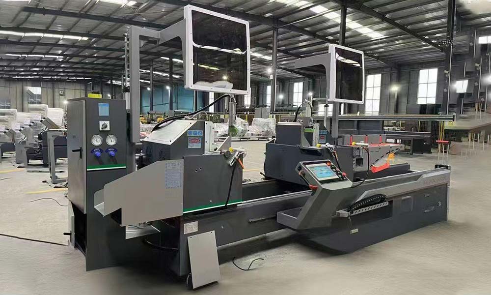
Moving from conventional three-axis milling to four-axis machining is not simply a matter of adding another movement to a CNC system. The real change is in how the machine can approach a workpiece, how often the operator needs to reposition it, how fixtures are designed, and how the complete machining sequence is programmed.
A cnc 4 axis milling machine adds controlled rotary movement to the familiar X, Y and Z linear axes. This additional motion can make multi-side machining, rotational features, long-profile processing and certain complex geometries much more practical. However, the value of the fourth axis depends heavily on the part geometry, workholding method, controller capability, tooling strategy and production workflow.
At its foundation, computer numerical control uses programmed instructions to control machine-tool movement. In modern machining workflows, CAD and CAM systems are commonly used to prepare geometry and toolpaths before machine instructions are generated for the controller. For four-axis machining, that digital workflow becomes especially important because linear movement must be coordinated with controlled rotation.
This guide explains what four-axis technology actually changes, where it delivers meaningful manufacturing advantages, where its limitations appear, and what you should evaluate before selecting a machine.
What Is a CNC 4 Axis Milling Machine?
A cnc 4 axis milling machine is a CNC milling system that combines three linear axes with one controlled rotary axis. On a conventional three-axis machine, the cutting tool and workpiece move relative to each other along X, Y and Z. A four-axis configuration introduces rotation, commonly identified as the A, B or C axis depending on the direction and machine architecture.
The most familiar arrangement uses an A-axis that rotates the workpiece around the X-axis. Instead of removing a component from the fixture, rotating it manually and locating it again, the machine can reposition the workpiece under CNC control. This is especially useful when features must be machined around several faces or around part of a cylindrical surface.
The important point is that the fourth axis should not be viewed only as an extra positioning device. When the rotary axis is properly integrated with the controller and CAM strategy, it becomes part of the overall machining process.
Understanding the Fourth Axis
The fourth axis may operate as an indexing axis or as a continuously controlled machining axis.
With indexed machining, the rotary axis turns the component to a specified angular position, stops, and allows conventional milling operations to take place. The machine may process one face, rotate the workpiece by a programmed angle and then process another face.
With simultaneous four-axis machining, the rotary axis can move while one or more linear axes are also moving. This makes more complex wrapped, helical or rotational toolpaths possible.
These two approaches place very different demands on the controller, CAM software, machine structure and operator knowledge, so they should not be treated as interchangeable simply because both systems are described as four-axis machines.
How CNC 4 Axis Milling Machine Technology Works
The basic machining principle remains material removal with a rotating cutting tool, but the additional axis changes the relationship between the cutter and the workpiece.
In three-axis machining, reaching another face often requires another setup. Each new setup introduces decisions about datum location, clamping, part orientation and verification. A rotary axis can bring additional surfaces into the machining area while maintaining the workpiece within the same fixture.
This can shorten the process route for suitable parts, but fewer setups alone do not guarantee a better result. The fixture must remain rigid throughout rotation, the rotary axis must position reliably, the tool must retain safe clearance, and the program must account for the changing orientation of the component.
For this reason, effective four-axis machining should be considered as a coordinated system rather than a single machine feature.
Indexed 4-Axis vs Simultaneous 4-Axis Machining
Indexed four-axis machining is often suitable for parts that contain identifiable machining faces at different angles. A component may require holes, pockets, slots or milled surfaces on several sides, while each individual operation can still be completed using conventional three-axis tool motion.
Simultaneous four-axis machining becomes more relevant when the required cutting path follows a rotating surface. Instead of stopping at several fixed angular positions, the workpiece rotates continuously while the cutter moves along its programmed path.
The correct choice depends on geometry. Purchasing a machine capable of complex simultaneous movement provides little practical benefit if most components only require controlled indexing. Conversely, an indexing-only solution can become restrictive if your normal work includes helical paths, wrapped features or continuously changing tool contact.
Core Components That Affect 4-Axis Milling Performance
Machine specifications are often compared using spindle power, travel and speed, but these figures alone do not describe how well a cnc 4 axis milling machine will perform in real production.
The rotary system is one of the first areas to evaluate. Its usable diameter, load capacity, positioning behavior, clamping mechanism and structural stiffness determine which parts can be supported and how reliably they can be machined. A rotary unit that is technically capable of turning a large component may still be unsuitable if fixture weight, cutting force or tool clearance pushes the system beyond its practical working range.
Workholding deserves equal attention. Long parts may require additional support, while cylindrical or irregular components may need dedicated fixtures. The objective is not simply to hold the workpiece tightly. The fixture must maintain a repeatable datum while allowing the programmed rotation to occur without collisions.
Spindle characteristics should be evaluated against the material and tooling used in normal production. Servo response, machine structure, controller capability and feedback systems also influence how consistently programmed movement becomes actual tool movement.
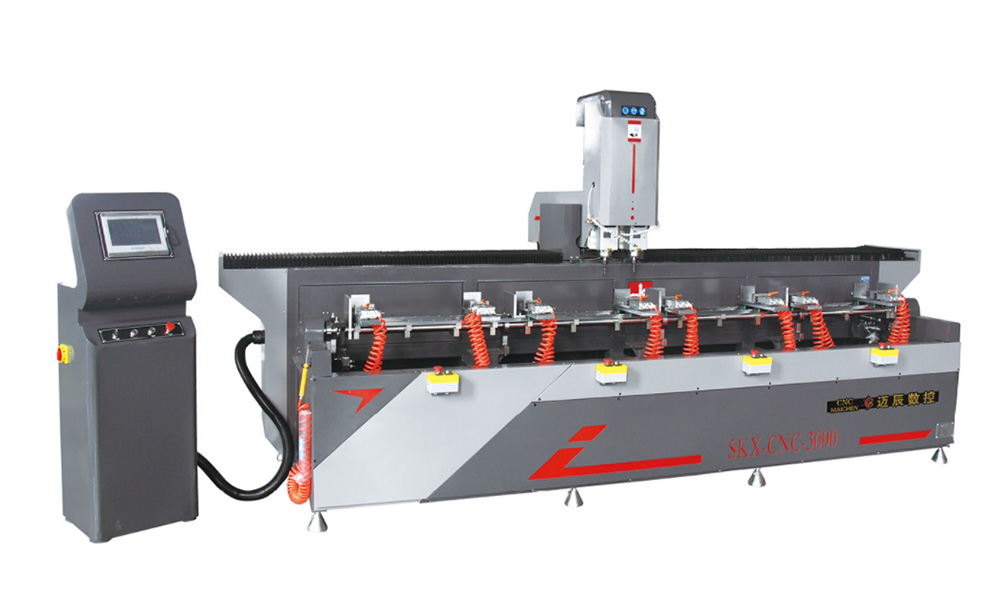
Automatic tool changing can be particularly valuable when a part requires drilling, milling, slotting and other operations during one setup. For example, MCS offers a 4-Axis CNC Aluminum Profile Machining Center that combines four-axis profile processing with an automatic tool-changing configuration, illustrating how the rotary axis can form part of a broader multi-operation machining system.
The more important selection question is therefore not “How many features does the machine have?” but “Do these features support the machining sequence my parts actually require?”
Where CNC 4 Axis Milling Machines Are Most Useful
The strongest applications for four-axis machining are usually parts where controlled rotation eliminates unnecessary handling or enables geometry that would otherwise require more complicated setups.
Multi-side components are an obvious example. If a workpiece needs drilling, pocketing or slotting on several faces, the fourth axis can rotate the part between operations while preserving the original workholding reference. This can simplify process planning and reduce the number of independent setups that must be recreated by the operator.
Rotational and cylindrical components are another important group. Slots, holes, repeated features and certain contours distributed around a circumference can often be programmed more naturally when the workpiece itself can rotate under CNC control.
Long extrusions and profiles can also benefit from four-axis capability when features occur on multiple orientations along their length. In these applications, machine travel, fixture arrangement, profile support and tool accessibility can be just as important as the existence of the fourth axis itself.
However, not every complicated-looking part requires four-axis machining. If all critical features can be accessed efficiently from one orientation, a three-axis machine may remain the simpler solution. Four-axis capability becomes valuable when the additional movement solves a recurring manufacturing problem rather than merely adding specification value.
CNC 4 Axis Milling Machine vs 3-Axis and 5-Axis Machining
Choosing between three-, four- and five-axis systems should begin with the workpiece rather than the machine category. More axes can provide greater freedom, but greater freedom also creates additional requirements for programming, collision management, fixture design and operator understanding.
| Comparison Factor | 3-Axis Milling | 4-Axis Milling | 5-Axis Milling |
|---|---|---|---|
| Controlled motion | X, Y, Z | X, Y, Z plus one rotary axis | X, Y, Z plus two rotary axes |
| Multi-side machining | Often requires repositioning | Well suited to rotation around one primary axis | Strong access from multiple orientations |
| Cylindrical features | More fixture changes may be required | Often highly suitable | Suitable but may exceed practical need |
| Programming complexity | Lower | Moderate | Higher |
| Fixture planning | Relatively straightforward | Must account for rotary motion | Must account for greater angular movement |
| Collision considerations | Moderate | Higher around rotary fixtures | More complex |
| Best fit | Accessible prismatic parts | Multi-side and rotational parts | Highly complex multi-angle geometry |
The table should not be interpreted as a simple ranking from basic to advanced. A five-axis machine is not automatically the best machine for every four-axis application, just as a four-axis system is not automatically more suitable than a three-axis machine for a straightforward plate.
A well-matched cnc 4 axis milling machine occupies a practical middle ground when one controlled rotational degree of freedom removes repeated setups or enables the required geometry without introducing a second rotary axis that the production process rarely uses.
How Workholding Influences 4-Axis Machining Results
Workholding is one of the most underestimated parts of four-axis machining.
When a fixture remains stationary, its main job is to resist cutting forces while maintaining the datum. When the fixture rotates, its mass distribution, clearance envelope, clamping rigidity and relationship to the rotary center also become important.
A tall fixture can increase the distance between the cutting force and the rotary-axis support. An oversized clamp can interfere with tool access at certain angles. A poorly centered workpiece can create unnecessary rotational load. A fixture that blocks one critical feature may eliminate the setup-saving advantage that justified four-axis machining in the first place.
For this reason, fixture design should be considered during process planning rather than after the machine has already been selected.
A useful approach is to model the workpiece, fixture, rotary unit, cutting tool and holder together in the CAM environment. The question is not only whether the cutter can reach a programmed feature, but whether the entire tool assembly can reach it safely throughout the rotary motion.
This approach is particularly important for long tools, deep pockets and components with large differences in radial dimension.
Programming and CAM Considerations for 4-Axis Milling
Programming a cnc 4 axis milling machine requires a clearer understanding of orientation than conventional three-axis programming.
For indexed work, the programmer must define the correct rotational position for each machining section and maintain a consistent relationship between the workpiece datum and rotary center. Errors in this relationship can appear on every indexed face even when the individual milling operations are programmed correctly.
For simultaneous machining, toolpath quality becomes more sensitive to how the CAM system converts part geometry into coordinated linear and rotary motion. Abrupt rotary movement, unnecessary reversals or poor tool orientation can reduce machining smoothness and increase cycle complexity.
Post-processor compatibility is therefore critical. A CAM system may be capable of creating an appropriate four-axis toolpath, but the final machine program still has to match the controller, axis configuration and kinematic behavior of the specific equipment.
Simulation should also be treated as part of programming rather than as a final visual check. The most useful simulation includes the actual machine envelope, fixture, rotary device, cutting tool and holder wherever possible.
This allows programmers to identify situations in which the cutter path itself is technically valid but the holder, fixture or workpiece becomes unsafe as the rotary axis changes position.
How to Select a CNC 4 Axis Milling Machine
Selection should begin with representative parts.
Collect several components that reflect normal production, including easy work, difficult work and parts expected to become more common in the future. Review their dimensions, materials, tolerances, machining faces, required tools and fixture requirements.
Next, identify why the fourth axis is needed. If the main objective is to machine four sides without repeated manual repositioning, indexed rotation may satisfy the application. If the geometry contains continuous rotational features, simultaneous capability may be more important.
Then examine the working envelope after fixtures are installed. Published axis travel does not always represent usable cutting space. Rotary devices, clamps, tailstocks, supports and long tools can reduce the practical envelope significantly.
The machine structure should also be considered in relation to expected cutting conditions. A high-speed profile application and a heavier material-removal application may require different spindle, rigidity and workholding priorities even when both use four-axis motion.
Controller and software compatibility should be evaluated before equipment selection is finalized. If existing CAD/CAM workflows cannot reliably generate the required programs, the practical cost of integration is not simply a software issue; it affects training, programming time and process reliability.
A broader discussion of how machine architecture should follow the workpiece and production process is also reflected in MCS’s 2026 CNC Machine Center Strategy, where four-axis capability is considered in relation to multi-orientation machining rather than as an isolated specification.
Common Selection Mistakes to Avoid
One common mistake is choosing a four-axis machine because it appears more versatile without first identifying which parts actually need rotary movement. If the rotary axis remains unused for most production, additional mechanical and programming capability may create complexity without improving the process.
Another mistake is evaluating only maximum workpiece dimensions. A component may physically fit the rotary system but still become impossible to machine because the fixture, cutter or spindle cannot maintain clearance at required angles.
Programming capability is also frequently underestimated. The machine, controller, CAM system and post processor form one chain. A weakness anywhere in that chain can limit how effectively the fourth axis is used.
It is equally risky to assume that fewer setups automatically mean higher accuracy. Reducing repositioning can remove some sources of setup variation, but overall machining accuracy still depends on machine condition, rotary-axis positioning, fixture rigidity, tool condition, thermal behavior, cutting parameters and measurement strategy.
Finally, avoid selecting from specification sheets alone. A more reliable evaluation uses actual part drawings or representative machining tasks. This forces the discussion toward tool access, cycle structure, workholding and program strategy instead of marketing specifications that may have little influence on your daily production.
How to Maintain Stable 4-Axis Machining Performance
Stable four-axis machining depends on maintaining both the conventional milling system and the rotary system.
The rotary axis should be kept clean and inspected according to the machine manufacturer’s maintenance requirements. Fixtures, chucks and locating surfaces need particular attention because contamination or damage at the workholding interface can affect the position of every feature machined after rotation.
Tool condition should also be monitored systematically. A program can repeat exactly while the cutting result changes because of tool wear, incorrect tool length data or changing cutting conditions.
Periodic verification of the rotary center is useful when applications depend on accurate relationships between features machined at different angular positions. If the machine or fixture has experienced a collision, unusual load or maintenance intervention, this relationship should be checked before critical work resumes.
Program management also contributes to repeatability. Once a machining process has been validated, the associated program version, fixture arrangement, tool list, offsets and inspection requirements should be controlled together. Treating the CNC file as the entire process record leaves too many variables dependent on operator memory.
When Does a 4-Axis Machine Make More Sense Than Another Configuration?
A cnc 4 axis milling machine makes the strongest case when one rotational degree of freedom solves a repeated production challenge.
If a component regularly needs machining around one principal axis, the fourth axis can substantially simplify the process. If a family of parts shares similar rotational or multi-face geometry, reusable fixtures and machining strategies can make the benefit even more meaningful.
By contrast, a component requiring access from many changing tool angles may justify five-axis evaluation. A straightforward component with features concentrated on one face may remain more efficiently produced on three-axis equipment.
This means axis count should be treated as a process decision, not a performance ranking.
The most useful question is therefore not “How many axes should I buy?” It is “What movement is required to machine my normal parts with the fewest unnecessary setups, practical programming complexity and reliable access to every critical feature?”
That question leads to a much more defensible machine decision.
Conclusion
A cnc 4 axis milling machine can create a valuable bridge between conventional three-axis machining and more complex multi-axis systems. Its main advantage is not simply additional motion. The real value comes from using controlled rotation to simplify workpiece orientation, reduce unnecessary repositioning and create practical access to features distributed around a component.
However, effective four-axis machining depends on much more than the rotary unit. Machine rigidity, rotary-axis capability, spindle characteristics, workholding, tool clearance, controller functions, CAM strategy, post processing and operator knowledge all influence the result.
For that reason, equipment selection should begin with actual parts and actual process requirements. Study how the component will be held, which surfaces must be reached, whether rotation is indexed or simultaneous, which tools are required and how the complete program will be validated.
When those questions are answered before machine selection, four-axis technology becomes more than another specification. It becomes a deliberate part of a stable manufacturing process.
FAQ
What is a CNC 4 axis milling machine?
A CNC 4 axis milling machine combines three linear axes with one controlled rotary axis. The added rotation allows the machine to reposition or continuously rotate a workpiece, making it useful for multi-side machining, cylindrical features and components that would otherwise require repeated manual setups.
What is the difference between 3-axis and 4-axis CNC milling?
Three-axis milling controls movement along X, Y and Z. Four-axis milling adds controlled rotation around another axis. This can allow additional faces or rotational features to be machined without repeatedly removing and repositioning the workpiece, depending on part geometry and fixture design.
Is 4-axis CNC milling suitable for cylindrical parts?
Yes, many cylindrical and rotational parts are well suited to four-axis machining because the rotary axis can position different areas of the circumference in relation to the cutting tool. Suitability still depends on component diameter, length, workholding, cutter access and the required machining operations.
What should I consider when choosing a CNC 4 axis milling machine?
Evaluate actual part dimensions, materials, required machining faces, rotary capacity, usable working envelope, spindle characteristics, fixture arrangement, controller functions and CAD/CAM compatibility. The best machine is the one whose axis configuration matches your normal machining process.
Do I need indexed or simultaneous 4-axis machining?
Indexed machining is often sufficient when a part needs conventional milling on several fixed faces. Simultaneous four-axis machining is more appropriate when the rotary axis must move during cutting, such as certain wrapped, helical or continuously changing rotational toolpaths. Part geometry should determine the choice.